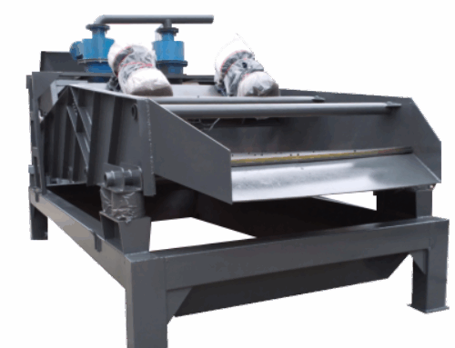
The sawtooth wave jig is one of the modern gravity separation equipment. Due to its high processing capacity, wide range of separation particle sizes, and simple operation and maintenance, it is widely used for roughing or concentrating minerals such as placer gold, tin, titanium, hematite, iron ore, and coal. It has particularly found extensive application in the beneficiation of manganese ore and barite.
Product Overview
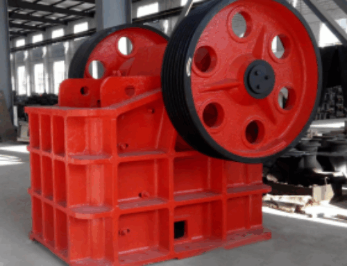
Traditional jigs are mostly driven by circular eccentric mechanisms, with pulsation curves that are primarily sinusoidal. Because the rising and falling water flow speeds and action times generated by the diaphragm movement are essentially the same, it is not conducive to the loosening of the jig bed and the stratification of mineral particles by specific gravity, thus affecting the separation ratio and recovery rate of the equipment.
The sawtooth wave jig is an energy-saving gravity separation device developed and improved based on the stratification theory of the jig bed. Its pulsation curve is sawtooth-shaped, making the rising water flow faster than the falling water flow: short rising time, long falling time. This overcomes the defects of the sinusoidal pulsation curve jigs, where the rising and falling water flows and action times are the same, enhancing the looseness of the bed, alleviating the suction effect, and allowing heavy mineral particles to settle fully. This significantly improves the separation ratio and recovery rate of the equipment.Compared to sinusoidal jigs, it improves recovery rates for Sn by 3.01%, W by 5.5%, Pb by 1.63%, and Zn by 2.04%. Water consumption is reduced by 30%-40%, and the footprint is reduced by one-third. Additionally, the stroke can be adjusted, and the number of strokes can be continuously adjusted due to the use of an electromagnetic adjustment motor. Its performance reaches the advanced domestic level, making it one of the ideal energy-saving gravity separation devices currently available.
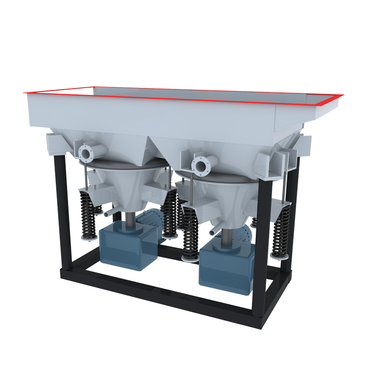
Product structure and principle
Type
The sawtooth wave jig is divided into two types, left and right, based on the installation position of the supply water pipe flange. Standing at the feed trough end and looking towards the discharge port, the water supply pipe on the left is the left type, and vice versa for the right type.
Model
The model of the sawtooth wave jig consists of the sawtooth wave jig, the area of the mineral selection chamber, and the number of chambers. The model description is as follows:1.Equipment InstallationThe jig must be installed on a level foundation to ensure the screen in the trough is inclined within the design range.
1.Installation of equipment
The jigger must be installed on a horizontal foundation with the bottom of the frame, ensuring that the inclination of the screen inside the tank is within the design range.
2.Adjustment
(1) Stroke Adjustment
The sawtooth wave jig can be equipped with either M12 or M17 cams according to mineral processing needs. If the user does not specify otherwise when ordering, the equipment will be shipped with the M17 cam installed. The stroke adjustment must be done while the machine is stopped, following these steps:
*1 Drain the lubricant from the cam box.
*2 Open the rear cover of the cam box.
*3 Loosen the spring group supporting the cone hopper so that the roller in the cam box is 5-10mm away from the cam.
*4 Use a special wrench to loosen the set nut on the cam.
*5 Remove the cam and replace it or adjust the relative angle between the cam and the drive shaft according to the mineral processing requirements, referring to Figure 4 (Cam Adjustment Angle and Stroke Relationship Curve) to change the stroke of the equipment.
After completing the stroke adjustment, reinstall in the reverse order of the above steps.
(2) Stroke Frequency Adjustment
The stroke frequency of the equipment is achieved by changing the motor speed. The ratio of stroke frequency to motor speed is 1:6. Adjust the motor speed by regulating the electromagnetic motor control device to meet the mineral processing requirements.
(3) Spring Adjustment
The spring group of the equipment helps reset the cone hopper upwards. Adjusting the compression of the spring group must be done while the machine is stopped. Ensure the compression of each spring in the group is roughly the same (measure the compression length of the springs) and that the roller in the cam box contacts the cam well. It is preferable to adjust so that after normal operation, the roller and cam do not produce a contact impact sound. Avoid over-tightening to prevent increasing friction between the roller and cam, which could increase the load on the equipment and accelerate wear of parts.
3.Use
(1) Matters for attention in use
When the equipment is in use, please read this manual and master the scope of the equipment and its operation.
Equipment motor power supply for three-phase AC 380V, electromagnetic speed motor control device using power supply voltage of 220V, its use, please refer to the electromagnetic speed motor control device instruction manual (see annex) for installation and operation, before turning on the power supply, you should check whether the power supply voltage is in accordance with the provisions of the various line connection is in accordance with the provisions of the various lines in the linkage is correct, the sieve under the water pressure is in line with the requirements of the water supply, fasteners Whether the fasteners are loose, collision, friction or extrusion, whether the drive shaft rotation is flexible, no stagnation (in the case of relaxing the spring group rotation).
(2) Requirements for use
The equipment can be equipped with different sieve specifications of the screen, the user did not specify in the order, the equipment is only equipped with 6 * 6mm specifications of the screen, when the equipment is used for separating less than 5mm fine materials, the use of sieve discharge method, this time, it is necessary to lay an artificial bed layer on the screen, the artificial bed layer used in the bedrock of the density, size, shape and thickness of the bedrock on the discharge of the heavy products of the rate of discharge and the quality of the impact of the product, for this reason, on the The choice of artificial bedrock should be:
*1 artificial bedrock particle size to reach the large size of the ore into the selection of 3-6 times, and 1.2-2 times larger than the sieve size, and the specific gravity is close to or slightly less than the specific gravity of heavy minerals is appropriate, so that the bedrock can always be kept at the bottom of the bed, and there are appropriate gaps to allow the passage of the heavy minerals and fine particles, the production of magnetite and other materials are usually selected to meet the above requirements as an artificial bedrock laying.
*2 The thickness of artificial bedrock paving affects the concentrate and quality, processing easy to select ore or according to the requirements of mineral processing needs to get a larger concentrate yield, artificial bed can be thinner, processing low-grade ore or according to the requirements of mineral processing needs to get a higher-grade concentrate, artificial bed can be thicker, artificial bed paving thickness of general 30-60mm.
*3 For the particle size of artificial bed stone, laying thickness, should be adjusted appropriately in the beneficiation process, in order to achieve good beneficiation effect.
(3) Instructions for use
After confirming that the equipment meets the requirements of 3.1 and 3.2, it can be operated and used, and the operation sequence of the equipment is as follows:
*1 Open the replenishment water valve, after the jigging chamber is filled with water, adjust the replenishment water to meet the requirements of ore dressing.
*2 Adjust the knob of electromagnetic speed motor control device to small (counterclockwise rotation). Start the motor.
*3 After the motor speed is stabilized, slowly rotate the knob of electromagnetic speed control device (i.e. adjust the equipment stroke).
*4 Confirm the normal operation of the equipment, and then evenly feed the ore.
According to the nature of the ore to be selected, adjust the stroke of the equipment, stroke, replenishment of water, so that the equipment to achieve a good beneficiation effect.
When the equipment needs to be shut down, it must stop feeding the ore, and then reduce the stroke to a small amount before stopping the power supply of the main motor.
4 Equipment lubrication
The equipment adopts shallow oil lubrication, the cam box is lubricated with 30# mechanical oil, the amount of oil injection to ensure that the transmission of large gears immersed in the oil surface 30-50mm appropriate, the new equipment, half a month to replace the lubricating oil, clean the box once, and then replace the lubricating oil and clean the box once a season, the ball bearing parts lubricated with ZNG69-2 ball bearing lubricating grease, every six months to change the oil once.
Product Application Scope:
It is used to select gold, tin, tungsten, titanium, hematite, iron ore, coal and other minerals, especially in the field of manganese ore beneficiation.